Electronics

Electronics

Σάββατο 12 Μαρτίου 2016

Security with Radio and Pir Modules

This project is part of a failed project I had in mind, my basic aim was to make a 3 transmitter - 1 receiver construction, and have the 3 transmitters placed in different spots of a location and when someone pass in front of them they could send a radio signal to a receiver, which could be placed anywhere, unfortunatelly I had to find out by the hard way (after lot of trial & error and lot of reading) that this can't happen due to the fact that these transmitters work at 433 Mhz and when more than one transmitters are turned on, the signals of them conflict and the result is random, most of the time they didn't work, but when only one transmitter is on the system works like a charm, well what can you say....you get what you pay and for 1 euro this pair is good for its money.

Have in mind to increase the distance we have to make some modifications :
A) Supply more than 5V voltage to the transmitter, this can happen when you overlap the 7805 part and supply it directly toe its pin.
B) In arduino programming keeping "vw_setup" at low numbers, I have it at 600 which is very good
C) Place a wire both at receiver and transmitter acting as an antenna which should be around 17.3 cm

Following these advices we can have the best results at the distance part.

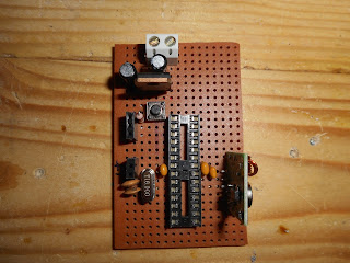
The whole project isn't hard to construct and it's arduino free, meaning that it can be programmed through arduino environment and later work completelly independent, following the pictures and the schematics it should take you a couple of hours to construct.

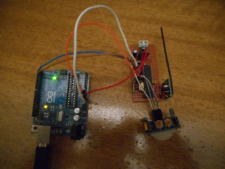
P.S. you will see a green wire at the receiver which was my first antenna, but it didn't work well so I had to modify it and place a straight 17.3 cm brown cable. Also you will see 3 leds, the reason was that in the beginning I had in mind to make 3 transmitters but it didn't work, so you will only need just 1 led, and 1 buzzer, there is also a pot which controls the loudness of the buzzer and also a switch which turns on/off the buzzer.


Code and Virtual Wire library here : https://www.dropbox.com/sh/wnjl7x154wvsp72/AABP6oAhA4S7u2TGpAeVwX64a?dl=0

Rock Band With Electronic Components (Just for fun)


Κυριακή 14 Φεβρουαρίου 2016

Mini CNC Plotter with Arduino

A great project based on "Ardumotive_com's" and "BIGDOG1971's" instructables. Both are very good explained projects and you can take the basic idea how this project is working and how to make it from skratch. Their basic difference is at the end (at that part I had my problem but I'll come with it later) since they use different program to convert the inkfile's svg to gcode, by converting our draw or text to this extension and by running the gctrl program which is a patch for processing we can make arduino communicate with our physical world and start drawing. So for the programing part we need :
a)Arduino IDE
b)Processing, which can be downloaded from here : https://processing.org/
c)Gtcrl update, which can be downloaded from the link I provide at the end of the article
d)Inkspace, which can be downloaded from https://inkscape.org/en/download/windows/ (Authors of both articles suggest you should download version 0.48.5)
e)The program to convert the inkspace's files to g-codes, https://github.com/martymcguire/inkscape-unicorn


First of all we need 2 cd-rom drives so we can make the X & Y axis : 


After this we need to connect some wires from the motors, later on we'll speak how to recognise these two coils inside this stepper motor. After we solder 4 wires to the end of the motors it is advised to put some hot glue for more safety.


Next is to mark the 4 corners where we will drill to put the mounting screws so that we can put the drivers upon them. It is advised, for the Y axis, the bottom screws can be as close they can to the south base, on the other hand the X axis screws (which is rotated 90 degrees in comparance with the Y axis) should be at the top of their base. I used a trick with nuts and bolts so I can later fix the leverage of my construction!


Final step is to make the Z axis, here everybody makes he is own patent, I've destroyed one more cd-rom so that I could have a mechanism on rails which can go up and down later I've attached to this mechanism the servo motor, so when the motors moves up and left, this mechanism helps the pen to move up and down, all this construction is attached with hot glue to the X axis.


For the electronics parts the things are less complicated. I used a 7805 voltage regulator with a heatsink, so I can feed the 2 stepper motors, the 1 servo motor plus the 2 L293D drivers and the arduino. You can connect the input pin of the 7805 to the Vin of arduino if you want since the arduino has an on-board voltage regulator. Also we should add 2 capacitors in the input and the output stage of the voltage regulator, they should be around 10 μF/16 v. In the pictures you can see how I've connected them, also the way my motors are connected to the board help me switch the cables quickly so I can find the right order later on the setup.
The stepper motor inside has two coils (that's why we have 4 cables!!) now if we take a multimeter and turn the knob to the resistor it should show us an indication to the right 2 cables, we should mark these two, then the other two cables make the other coil of the motor so if we measure it we should have another indication.
So the first pair of cables are connected to pins 3 & 6 of L293 and the other pair to pins 11 & 14. The same applies for the X axis too. If everything is ready we connect our arduino to our pc and load the X-axis example and run it, if we see some move then we are on the right track, else we should change the connections until we see some move. We should follow the same route for the Y-axis, by loading the Y-axis example and watch for some movement in our construction and by changing the order of our cables until we see. Finally we should load the Z-axis example and see our servo move up and down. If everything is ok we should load the "cnc-plotter.ino" to our arduino and close the program, our chip is ready now! Now it's time for use of Gctrl and Inkspace but I won't enter in details since there are already great examples in the internet that you should follow!


And here is the schematic thanks to ardumotive and Mixalhs Vasilakhs for their great project :

As a final comment I would like to remind you what I've written in the beginning of this article, that basically I've followed 2 projects which are great, in the end when my plotter started to draw all the images were mirrored, after a bit of search since I was thinking that it had to do with a problem in inkspace i've come to the answer. Mixalhs and the friend from Brasil connect differently not only the motors but also the arduino outputs. So follow both methods for the mechanical build and mix their ideas but with the electronics stay with Mixalhs approach!

Arduino codes and schematics here : https://www.dropbox.com/sh/w1uu1q6a4jmmlld/AAANbGKyS_X6WNVEzAMzLVbua?dl=0


Πέμπτη 4 Φεβρουαρίου 2016

Firework Igniter

This project is based on great Scott's project from instructables. My basic difference is that I use an arduino mini clone which costs 2-3 $ while Scott uses an Atmega chip individually with the components required (crystal,capacitors,voltage regulator). I found it more easy and compact to use the clone. The whole trick is to send an amount of current to the resistors so they can burn, this command will be sent with our mobile phone, while the bluetooth module will receive and will energise the right transistor. Scott also had a voltage comparator which is being connected to analog pin 0 (A0) so that if the program see we have less than 5v and it will stop. Make sure to have the bluetooth module disconnected when you upload the program to arduino, also by reprogramming the app you can add more outputs, so more explosives can be connected!
The code and the app can be found here :
https://www.dropbox.com/sh/3ygdquejq10xg42/AACNF-hc46Oghhfn9L9Sq-gQa?dl=0

If you want you can visit : http://appinventor.mit.edu/explore/
and modify the app so that more fireworks can be connected!