Electronics

Electronics

Τρίτη 24 Μαρτίου 2015

RGB Led Strip Controlled by Bluetooth & IR

A few months ago I saw GreatScott's project which had an RGB led strip and he could control it through his tv control with an arduino and some more components including one MOSFET. This was an overkill since he had 3 colors and he choose to shortcircuit the legs and get just one color. In my version I use 3 MOSFETS to control each color separate. The whole project is based on Scott's schematic with the difference I use 3 MOSFETS and the resistor that connects arduino to the base of the MOSFET is 1K and not 10K like Scott suggests (it took me 3 days to find this problem)! Also I made some changes to the code since we have to do with 3 colors and not just one. When I finished building it another idea came to me, why not control it with my android phone also? Fortunatelly some people from Thailand which I don't know their names because it was in Thai were tenderhearted and offered the arduino code and android app for free. One positive point was that minor changes had to be done to the hardware part. A bluetooth module and connections to Vss,Gnd, Rx and Tx. Again I Had some problems in the code because there was a conflict between the bluetooth and the IR part but after some trial and error, everything worked perfectly. One crucial thing to do in the IR part is that because every controller-tv has a unique code depending on the manufacturer is to get the IR codes for the controller of the led strip by running the arduino example "IRRecvDemo". There by running the serial monitor and pressing the keys you want for control you should get 7 different codes (Red Up/Down, Green Up/Down, Blue Up/Down And Power On/Off-Same key), then you must replace these codes in the arduino code and everything should work fine. Finally as you will see in the schematic my bluetooth's Rx pin has a voltage divider which is 3.3 Volts and it works fine, manufacturer suggests this voltage cause arduino's 5V might burn it.

I provide the schematic and the arduino code for The IR controller separately if you want to build it individually. And also the schematic and the arduino code if you want to build the mixed version!
You can estimate for every meter you will need 1A power supply, so for a 5m RGB strip you will need a 12V / 5A Power Supply.

Android app : https://play.google.com/store/apps/details?id=arduino.control.rgbleds
Arduino code : https://www.dropbox.com/sh/g3yns970ma15up1/AAAswMf26Ml1UC3xgPBR8D0sa?dl=0


Κυριακή 15 Μαρτίου 2015

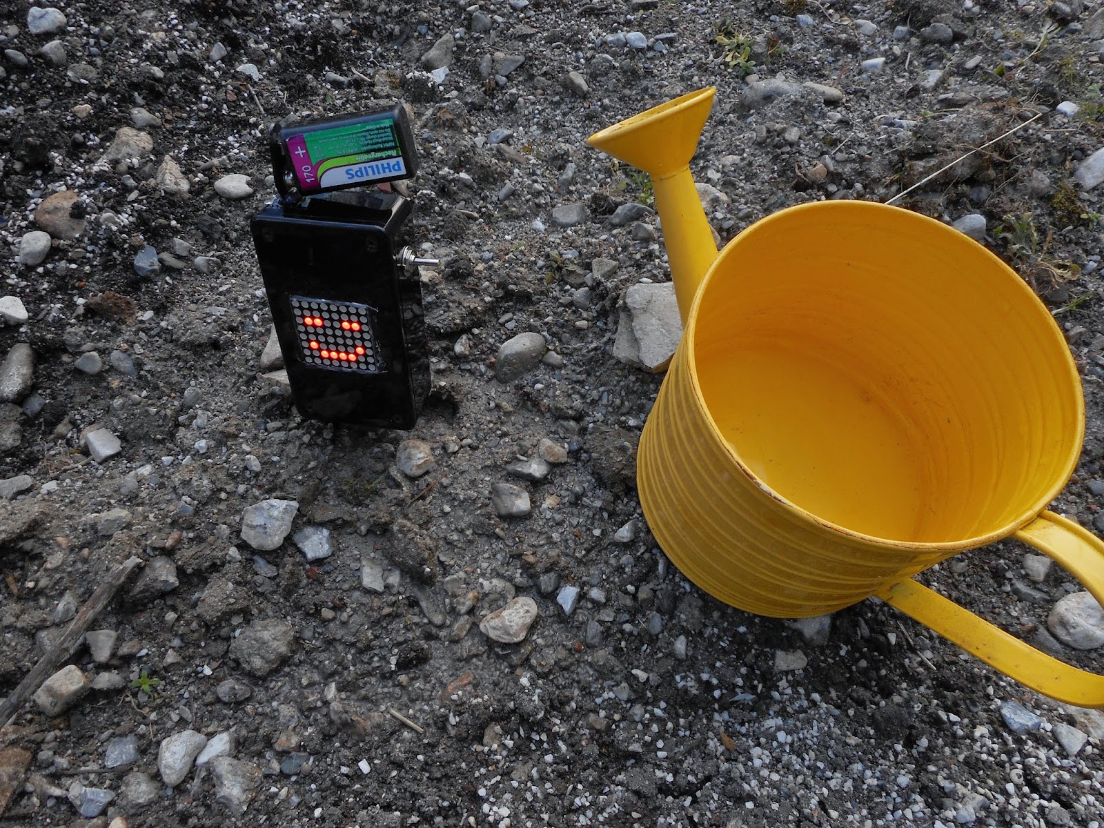
Make Your Plants Smile


A very nice project by thanasisloi7, which can be made in an evening. In his project he uses an ATtiny85 which he programs it through arduino, so if you haven't programmed an ATtiny before or you didn't make the circuit i had provided some days ago (how to programma ATtiny though arduino) you can make it by using only arduino with the only difference to change the pin numbers in the code, a procedure which takes about 10 secs! Also here are 2 links : http://www.pial.net/tools/  and  http://www.binaryhexconverter.com/binary-to-hex-converter , with the help of these two links you can give your 8x8 dot matrix any gesture you want by simply changing the lines in code : {0x00, 0x64, 0x62, 0x02, 0x02, 0x62, 0x64, 0x00},//0  and
{0x00, 0x22, 0x64, 0x04, 0x04, 0x64, 0x22, 0x00},//1,  these lines define the sad and happy face. As an extra, if you take the decision and make this circuit, ATtiny has an extra free pin (pin 3) and you can connect a transistor which will control a small pump to water your plants when they feel sad, this is just some extra lines code.

Arduino Code : https://www.dropbox.com/s/36f6ipzfvvawotc/smile_plants.ino?dl=0
 

Τετάρτη 11 Μαρτίου 2015

UV LED Exposure Box


Sometimes I make some PCBs with the photo resist method which is basically printing a project through a design software (eagle in my occasion) with a laser printer, exposing to UV light for an amount of time (10 mins) and through chemical solution-etching have the final product. I wanted to upgrade the old fluoroscent lamp my dad used to have so I made this pcb based on 2 ideas by "djhamer" and "bulb66" at instructables. This time I use 5mm Round Top Ultra Violet LED UV Light 3000MCD. The use of arduino as a timer, I find it as an extra with no use since 2 minutes now are very good for the exposure of a board. The schematic is very easy to follow and this is a project that can be finished in an afternoon. Lastly all the resistors are 1/4 watt and because I didn't had 75 R resistors I used in parallel 1 resistor of 100R and 1 resistor of 220 R which through the formula 1/R1 + 1/R2 = 1/Rr1,2 gave the final R which was nearly 70 R, and it was very good.

Κυριακή 8 Μαρτίου 2015

Bomb!! (For Airsoft Gaming....)

In this circuit I'm presenting you an airsoft bomb, the circuit is based on the excellent code by at instructables but with some minor modifications. I made it for a friend for mine so he can dress up as an terrorist for the carnival. I think the whole concept went quite well. In the circuit we have 3 wires and one button. Button is for adding seconds as more you press it, time is increasing. As for the 3 wires, One (the correct!!!) is for stopping time, the second is for decreasing time faster and the third one is for resetting time.
Basic changes I've made in comparison with ntewinkel's circuit are :
a) Using common cathode displays and not the LTC clock he suggests.
b) I didn't want my arduino to power the displays directly, so i've added some npn transistors.
c) D13 of arduino is an output which you can connect anything when time is over, I've programmed it so it can make a task for a small amount of time (in my occasion power a siren for 2 secs).
d)Add some resistors for more protection.

In the schematic you can find the connections but I'm writing here the values in case you can't read it well.

button:
5v - Button - A5 - 10k Resistor - gnd

crazy wires:
5v - RED jumper wire - A4 - 10k Resistor - gnd
5v - BLUE jumper wire - A3 - 10k Resistor - gnd
5v - YELLOW jumper wire - A2 - 10k Resistor - gnd

Action:
pin D13 is already hooked up to an LED

7 Segment Display   >   Arduino
           A                          D7
           B                          D8
           C                          D9
           D                          D10
           E                          D11
           F                          D12
          G                          A0
          Colon                   D4
          Digit1                   D2
          Digit2                   D3
          Digit3                   D5
          Digit4                   D6

All resistors at the base of transistors are 1K.
Resistors from the emmiter to 7 Segment Display are 220 Ω.
Resistors for grounding A5,A4,A3,A2 are 10k.
All NPN transistors are BC337.

Arduino Code : https://www.dropbox.com/s/sae7erugq1ibzpf/crazy_timer_with_delay.ino?dl=0


Σάββατο 7 Μαρτίου 2015

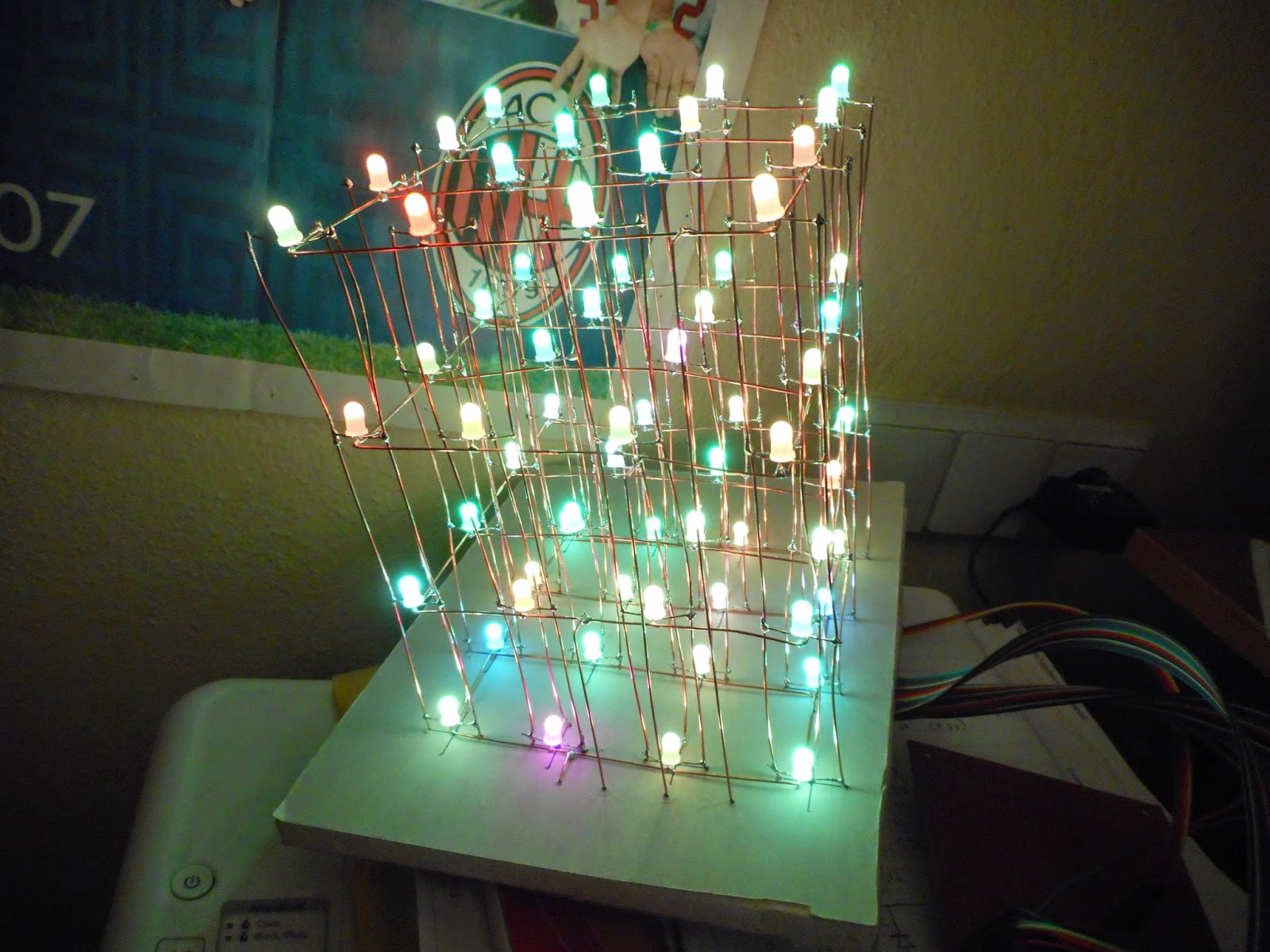
4X4 RGB Led Cube (With Common Anodes Leds)


Based on a wonderful project by GreatScott (https://www.youtube.com/channel/UC6mIxFTvXkWQVEHPsEdflzQ) I had to take a chance to make this cube. With informations Scott is providing the project became even easier to build. The hard part is the connection between the leds, once you finish with that, then in an evening you can complete the project. Based on 3 TLC5940 shift registers, which sink power (connecting to ground), for the cathodes of each color and 4 P-channel MOSFETS for the anodes of each layer and a small arduino you can make wonderful things.


Arduino Code : https://www.dropbox.com/s/z65e7fkgze0o75u/functionByKostas2.ino?dl=0