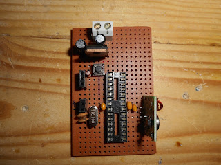
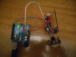
This project is based on sjowett's "How to 'bling' Up A Boring Staircase" which is very easy to be built. The main parts are 2 PIR sensors which detect the move of the person if he is in the upper or the bottom part of the staircase, a photoresistor which detects if it's day or night, depending on this resistance the light of the staircase might not light because who needs to turn on his staircase if it's a day? :) , finally we have our arduino and our WS2812B led strip with it's power supply.
Each RGB LED draws approximately 50 mA when it is set to full brightness and powered at 5 V. This means that for every 30 LEDs you turn on, your LED strip could be drawing as much as 1.5 A. Be sure to select a power source that can handle your strip’s current requirements. Also you need to put a capacitor between 100μF - 1000 μF near the + and - of the power supply, also a small resistor between 100-470 Ω to the data signal which connects arduino to led strip.
https://www.dropbox.com/home/Light%20Staircase
In comparison to the original sketch I had to do the followinf modifications :
1) int alarmValueTop = LOW; // Variable to hold the PIR status
int alarmValueBottom = LOW; // Variable to hold the PIR status
2) pinMode(alarmPinTop, INPUT); // for PIR at top of stairs initialise the input pin and use the internal restistor
pinMode(alarmPinBottom, INPUT); // for PIR at bottom of stairs initialise the input pin and use the internal restistor
3) if (alarmValueTop == HIGH && downUp != 2)
if (alarmValueBottom == HIGH && downUp != 1)
4) THE MOST CRITICAL! try this project in dark, because I was putting my hand in front of the LDR to raise the resistance while I had my light turned on the led strip wasn't performing how it supposed to do and while it started to work right eventually it was stopping. SO try this project at dark!


